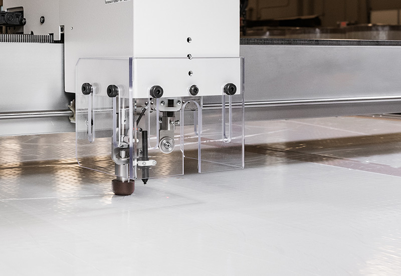
The use of a CAD cutting table empowers Electrolock in the prototyping and fabrication of parts used across a wide range of industries. The precision and efficiency afforded with the use of this device aids in quickly delivering proof of concepts and production for larger, two-dimensional parts. This process represents one way Electrolock provides insulation materials to its customers to further tailor solutions to specific applications.
Cutting tables, whether outfitted with traditional plasma cutting tools, lasers, or other implements, are some of the most finely-tuned, efficient, and versatile tools for producing finished parts or even additional tooling out of a vast assortment of materials. The computer-automated nature of CAD cutting tables allows for a precise cut and an extremely high level of accuracy for every repetition or process.
CAD (Computer Aided Design) refers to the use of computers in helping the creation, modification, analysis, or optimization of a design. Software is used to increase the productivity of the process, improve the quality of the design, and even create a database for further manufacturing. CAD files, containing either a 2D or 3D design, contain the blueprint, schematic, or technical drawing of an object. A CAD cutting table uses these files to produce the object in a precise and perfectly repeatable manner.
With the basics covered, it’s time to look at how using a CAD cutting table can benefit fabrication and manufacturing.
Thermal Performance: CAD table cutting is a common way to design special thermal insulation solutions. Examine Electrolock’s full set of offerings here.
Why Using a CAD Cutting Table is Essential
Because of their ease of use, setup, and rapid deployment time, the use of a cutting table is often prized in the prototyping stage. Once final drawings or schematics are set, it’s a relatively quick process to set up a CAD table for quickly cutting the desired part out of the chosen material to further the development process of the theorized solution to an engineering problem.
Another key use of the device is to manufacture tooling (once designed) that can then be used in other fabrication applications. For example, a CAD cutting table might be used in the creation of a die to be used later in a rotary die-cutting process.
Given the size and dimensions of a typical CAD cutting table, the device is best used for cutting out large, two-dimensional shapes or parts. Good examples would be larger, mostly flat, parts used in automotive or industrial applications (like gaskets), or shielding components in high-temperature thermal applications.
A CAD cutting table is best implemented when you need large parts quickly, and lots of them. If you already have the CAD file, you can go right to the production floor and get started nearly immediately. With the use of a CAD table, you can cut the time needed to transition from prototyping to full production. The use of CAD files leads to automation of the process, and the ability to go roll to roll with the materials needed without delays and with the consistency ensured by the computer-assisted design.
Flexible materials, those not especially dense or rigid, work best with CAD cutting tables for fabrication. This still leaves a wide range of possibilities, including (but not limited to):
- Laminates
- Glass
- Kevlar®
- Woven or non-woven fabrics
- Coated fabrics
- Film
- Fiberglass
While the strengths of a CAD cutting table are evident, there are still circumstances when other fabrication techniques may be preferred. For example, die-cutting is better equipped to handle the fabrication of complex parts or those that contain a lot of different cuts per inch. You’ll want to explore rotary die-cutting for medium to small parts in high volumes, for parts with more intricate shapes, or when you seek kiss-cut capability — commonly used for some material choices like foils, Nomex®, and Kevlar®.
CAD table cutting and die-cutting are just two of the fabrication processes available through Electrolock. Whatever form you need your materials converted to Electrolock can help with slitting and rewinding, coating and saturation, sheeting and shearing, spiral wound tubing, kitting and packaging, and much more.
Go Deeper with Rotary Die-Cutting: Learn more about why rotary die-cutting is commonly used in the fabrication of insulation solutions.
Electrolock has a Complete Line of Complementary Services
Electrolock has been engineering solutions for the high-voltage electrical, battery, and thermal insulation industries since 1957. Our focus has always and will continue to be, focused on creating bespoke — unique and tailored — solutions to service the most demanding requests.
Electrolock innovates and produces bespoke solutions for every client to fit the exact requirements of your specific applications. By collaborating with your business, Electrolock will design, fabricate, and then fully test potential solutions. By validating — through an extensive in-house testing system — before entering production, Electrolock is able to save both time and expense on the back-end of a project.
By choosing Electrolock, you won’t simply be picking a product from a catalog or menu of options. You’ll work with Electrolock’s experienced, expert-level team to create a custom-designed answer to your particular problem — complete with fabrication options.


